SkyRunners UAV
Manufacturing and structures lead. Active team project.
SkyRunners is a Stanford student team building a fixed-wing UAV system. I lead manufacturing and structures, which means turning design intent into actual parts that survive the loads they're supposed to survive, assembled in a way that can be reproduced and maintained.
Coordinate manufacturing across a team where design and build happen in parallel, while keeping structural integrity and weight targets intact throughout.
- Weight budget is non-negotiable. Every gram in structure is a gram out of payload or endurance.
- Parts need to be manufacturable with available tooling, not just theoretically optimal
- Airframe needs to be repairable in the field without specialized equipment
- Composite spar design for the main wing load path, with accessible bonding interfaces
- Modular fuselage sections so subsystems can be swapped without full disassembly
- Material selection driven by laminate schedule rather than raw material properties alone
- 01
Wing profile: E193 airfoil. First cores built by laser cutting plywood ribs, gluing to pink foam blocks, and manually cutting to shape. Worked, but introduced too much asymmetry.
- 02
Switched wing production to the 4-axis wire foam cutter at CHIP, which cuts root and tip profiles simultaneously from the CAD file. First cuts came out clean and symmetric.
- 03
Fuselage skinning: 1/32" balsa sheet over rib frames, heatshrink foil pulled tight over the balsa for a smooth aerodynamic surface
- 04
Full parametric redesign: rebuilt the model so chord, span, rib spacing, fuselage cross-section, and tail geometry all drive from a single parameter table instead of being manually updated
- 05
CFD in Luminary: current design has CoP too far aft. Elevators need negative AoA to trim, which is a drag penalty. Geometry revision in progress.
Active development. Wing production process validated. Aerodynamic layout under revision based on CFD.
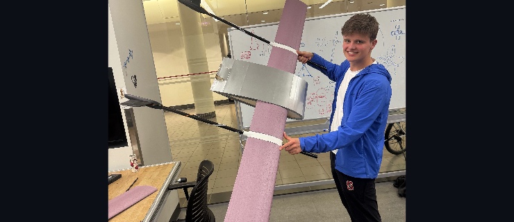
Carbon fiber spar rods cut and clamps printed to fix motor twist
Cut four carbon fiber rods to length and 3D-printed four clamps to mount them to the existing airframe. The spars run spanwise from the main fuselage structure to brace the motor booms and stop them rotating out of plane under load.
Rods cut cleanly to the correct length. All four clamps printed and test-fitted to the airframe — tolerances are correct, clamping force is good, and nothing needs to be rebored. Used a respirator and full PPE throughout the cutting process; carbon fiber dust is not something you mess around with.
Full systems test: motors and servos under load
With the airframe fully assembled — motors on mounts, ESCs wired, servos connected to the flight controller and linked to control surfaces — ran the first full systems test. Spun all four motors up to partial and full throttle and exercised all control surfaces through their full range under load.
All four motors spun up cleanly with no ESC faults. No resonance or vibration coupling into the tail linkages at any throttle level. Servos held position under motor wash and responded correctly to stick inputs throughout. Power bus stayed stable — no brownouts or voltage dips that affected the FC. Elevator and rudder throws matched the configured endpoints in both directions.
Control surface linkages installed and servo cables routed through tail boom
Installed pushrod linkages for the elevator and rudder, connected them to the control horns on each surface, and ran all servo cables through the tail boom to the fuselage.
Both elevator and rudder pushrods installed with correct throw and no slop at the clevises. Cables routed cleanly through the boom with enough slack at the fuselage end for servo connections. Control surfaces move through full range of motion with no binding.
Motor mounts and landing gear: designed, 3D printed, and assembled
Designed new motor mounts and landing gear in CAD, 3D printed both parts, and assembled them onto the airframe.
Parts printed cleanly. Motor mounts fit onto the boom tubes with the designed press-fit tolerance — no slop, no cracking. Landing gear attached and holds the airframe at the correct ground angle. Assembly went together without issues.
Carbon spars bonded to fuselage and tail
Glued the carbon fiber spars to the fuselage and bonded the tail assembly onto the carbon spars.
Bond came out clean. Spar alignment checked against the CAD reference and is within tolerance. Tail is square to the fuselage centerline. Epoxy cured fully overnight with no delamination or voids visible.
CFD in Luminary: CoP is too far aft
Ran full CFD analysis on the current wing and fuselage geometry in Luminary.
CoP came out significantly too far aft relative to our CG target. The aircraft as designed would be longitudinally unstable. To compensate, the elevators need to run at a meaningful negative angle of attack to trim, which is a drag penalty we don't want baked into the baseline.
Full parametric redesign
Rebuilt the entire airframe model parametrically in Fusion 360. Wing chord, span, rib spacing, fuselage cross-section, and tail geometry all driven by a single parameter table.
Model rebuilt. Changing the master parameters now propagates correctly through the full assembly. First test: swept chord from 180mm to 200mm, updated cleanly in about 30 seconds.
Fuselage skinning: balsa ribs + heatshrink foil
Covered the fuselage rib frames with 1/32" balsa sheet, then wrapped the outside with heatshrink foil.
Surface came out smooth. Heatshrink pulled evenly with a heat gun. No bubbling or wrinkles on the curved fuselage sections. Weight added was less than expected.
Wing cutting: switched to 4-axis wire foam cutter at CHIP
Moved wing core production from the manual method to the 4-axis wire foam cutter at CHIP (Stanford's product realization lab).
First cuts came out clean. Both wing halves match within tolerance. The profile edges are sharp and consistent in a way the manual method never got close to.
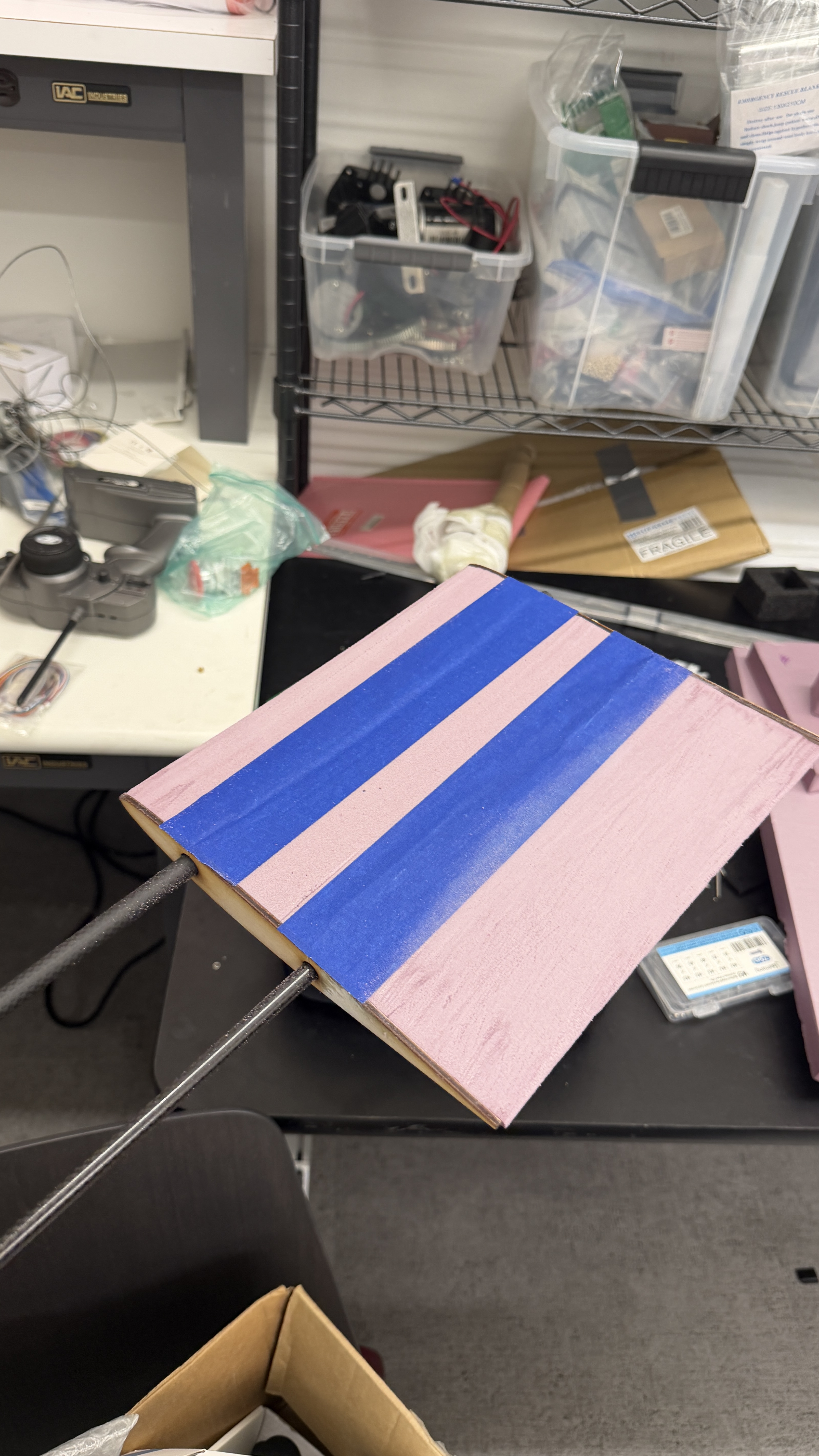
First wing cores: E193 profile, laser cut ribs and manual foam shaping
Cut the first wing cores using a laser-cut wood rib template method: laser cut E193 profile ribs from plywood, glued them to pink foam blocks as guides, then manually cut the foam to shape with a hot wire and knife and bonded the pieces together.
Wing core came out roughly correct in profile. Surface finish was rough and the manual cutting introduced some asymmetry, but good enough to validate the E193 geometry as workable and confirm the rib spacing layout.